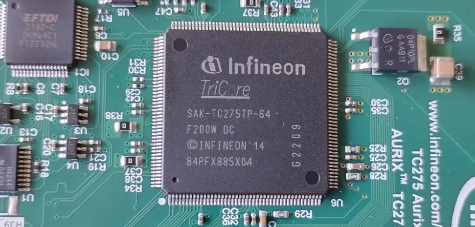
Demo – Implementing CAN on Aurix TriCore TC275


Recent Posts
-
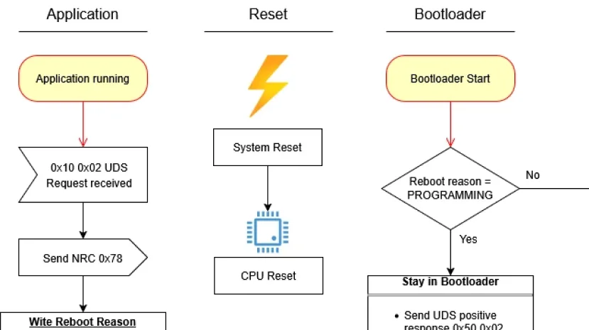
Protected: Handling Reboot Reason using non initialized RAM on Aurix TC27x
There is no excerpt because this is a protected post.
-
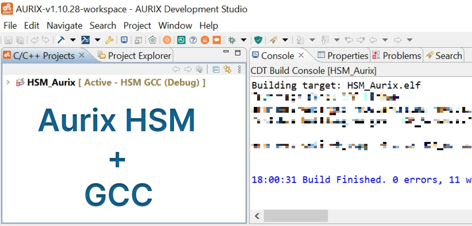
Protected: Building Infineon AURIX HSM Firmware with GCC in AURIX Studio
There is no excerpt because this is a protected post.
-
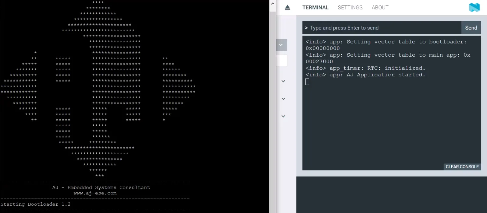
Protected: Implementing CAN on Aurix TC275 Lite Kit
There is no excerpt because this is a protected post.
Leave a Reply